
Raw LoRa Communication: Easy Setup & Demo!
Published by Vivian van Zyl in ESP32 Microcontrollers the 03/12/2025 at 11:19 pm

Welcome to the fascinating world of raw LoRa communication! Today, we are diving into the specifics of using the SX1276 chip to send and receive LoRa messages. This technology allows for incredible flexibility in building your own software and applications, going beyond frameworks like Meshtastic.
In this blog, we'll explore the setup process, the commands you can use, and how to connect different devices for effective communication. Let’s get started!
Table of Contents
- Understanding the Basics of LoRa Communication
- Setting Up Your Hardware
- Working with AT Commands
- Sending and Receiving Data
- Implementing the Sending Node
- Implementing the Receiving Node
- Testing the Setup
- Common Issues and Troubleshooting
- Conclusion
- FAQ
- Further Reading
Understanding the Basics of LoRa Communication
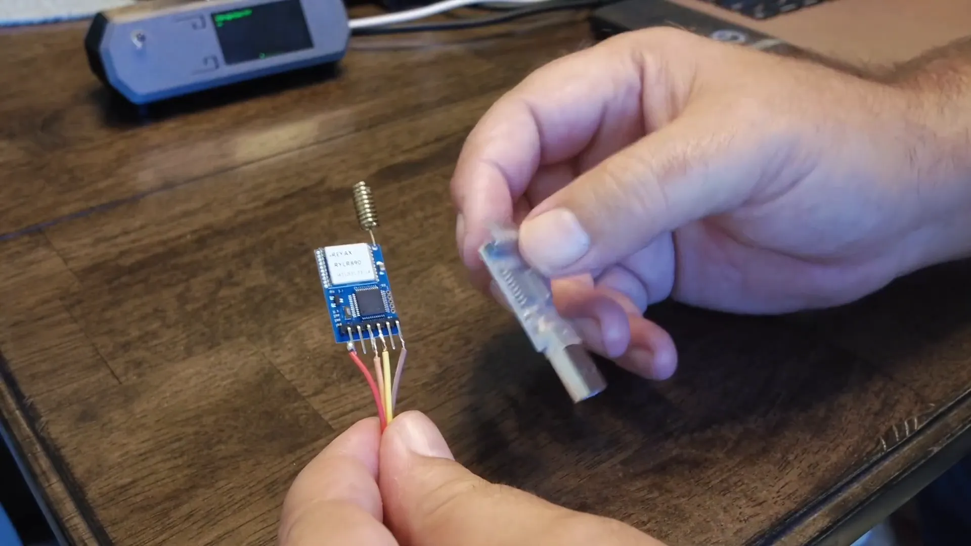
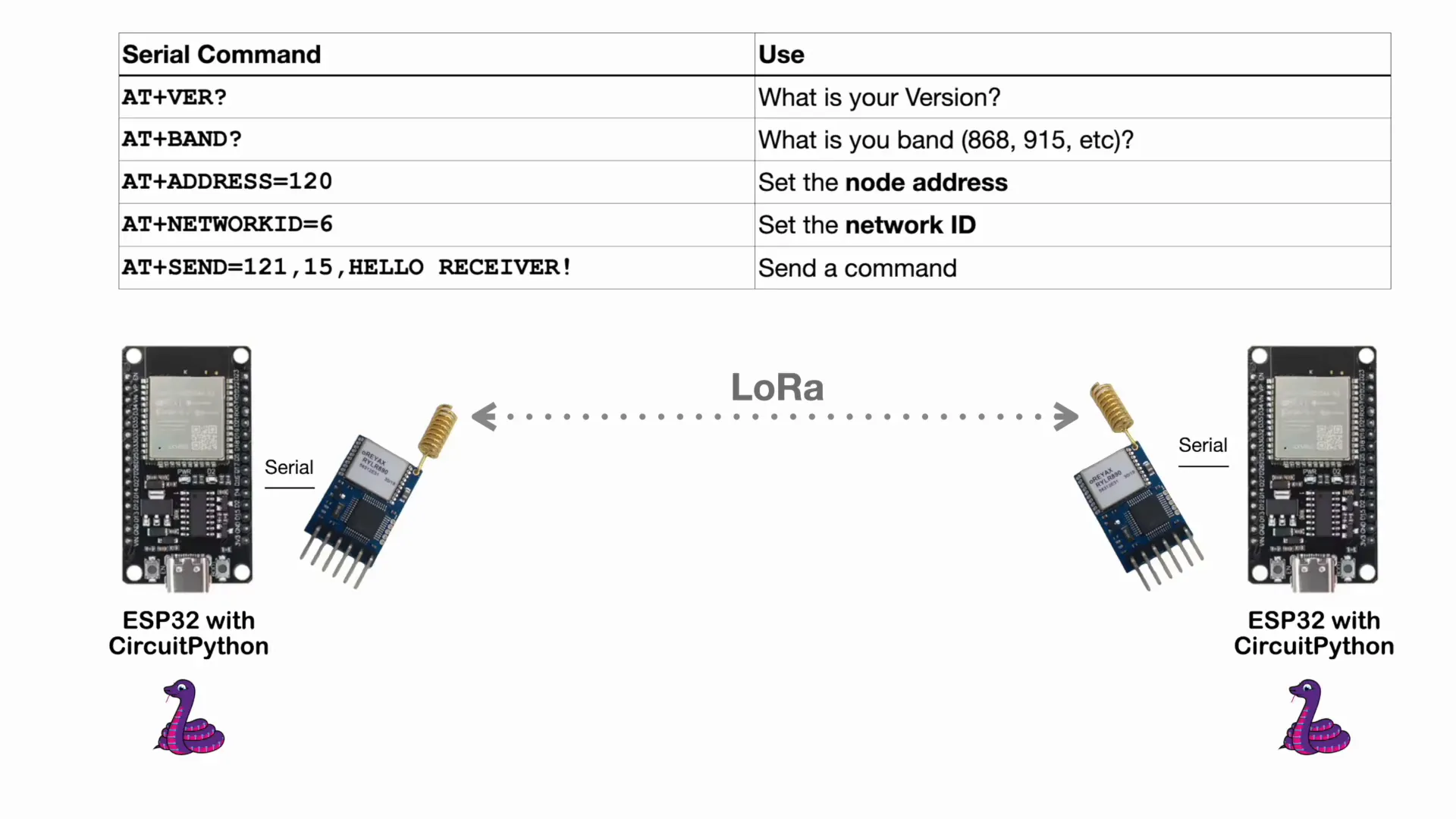
LoRa (Long Range) technology enables long-distance communication with low power consumption. The SX1276 chip is a UART type chip that facilitates this communication. To interact with the SX1276 chip, you’ll typically need a serial to USB converter. This converter connects to the chip via four wires: power (3.3V), ground, receive, and transmit.
Once connected, you can set the baud rate and send simple commands. For example, sending the command AT will prompt the chip to respond with OK, confirming the communication is established.
Setting Up Your Hardware
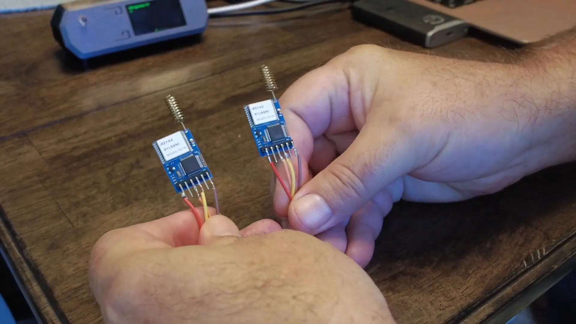
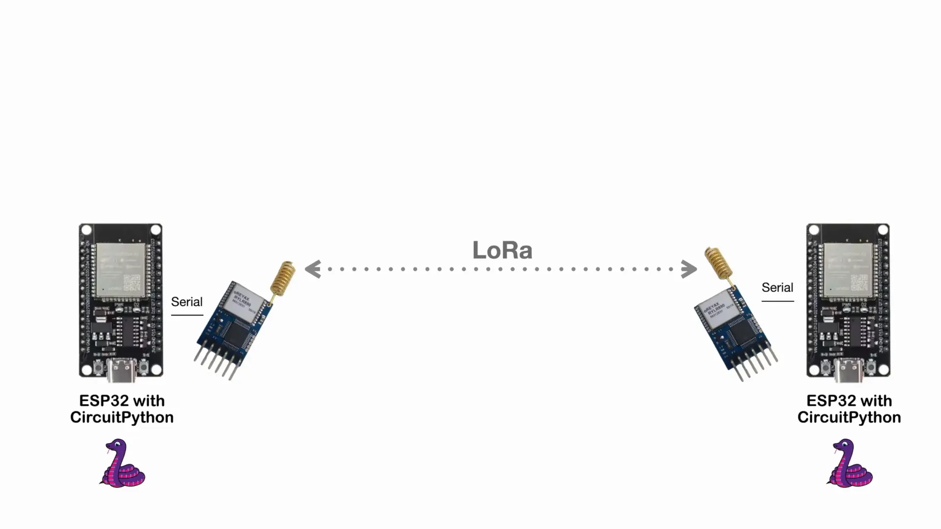
For this demonstration, I’m using two ESP32 microcontrollers connected to two SX1276 chips. The ESP32 is a versatile microcontroller that can run CircuitPython, making it a great choice for this setup.
The potential communication distance between these two devices can reach miles, thanks to the capabilities of LoRa technology. You can even connect sensors to one of the ESP32s to gather data and transmit it over long distances.
Connecting the ESP32 to the SX1276
To establish the connection, we need to load CircuitPython onto the ESP32. This is a straightforward process, and I’ll provide a link to a tutorial for those interested.
Once CircuitPython is loaded, you can connect the ESP32 to the SX1276 chip and start sending commands. For instance, you can set the communication parameters such as the band and node addresses.
Working with AT Commands
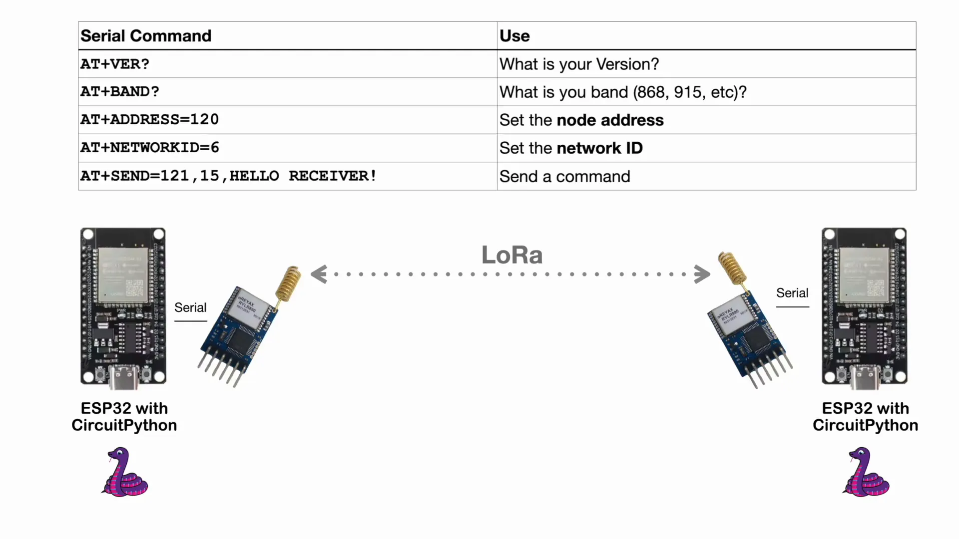
Once you have connected the ESP32 to the SX1276 chip, you can use AT commands to configure your devices. For example:
- AT+VER? - This command asks the chip for its version.
- AT+ADDRESS=120 - This sets the node address to 120.
- AT+NETWORK=6 - This sets the network ID to 6.
Each node can have its own unique address, allowing for hundreds of nodes across various networks. This flexibility is one of the key advantages of using raw LoRa communication.
Sending and Receiving Data
To send data, you can use the command format AT+SEND=
AT+SEND=121,15,Hello Receiver!\r\n
This command sends the text "Hello Receiver!" to the node with address 121. If you set the address to 0, it broadcasts the message to all nodes on the network.
In this setup, one ESP32 will act as the sending node and the other as the receiving node. Each can communicate with the other, allowing for bidirectional data transfer.
Implementing the Sending Node
Let’s take a closer look at the sending node’s code. The program initializes the LoRa module, sets the address, and begins sending messages at intervals. Here’s a simplified version of the code:
import time
import board
import busio
from digitalio import DigitalInOut, Direction
# Define the pins used for UART communication
UART_TX = board.IO17 # TX2
UART_RX = board.IO16 # RX2
LED_PIN = board.IO2 # Onboard LED
# Initialize UART
uart = busio.UART(UART_TX, UART_RX, baudrate=115200, timeout=0.1)
# Initialize the onboard LED
led = DigitalInOut(LED_PIN)
led.direction = Direction.OUTPUT
# Function to send AT commands and read response
def send_at_command(command):
"""Send AT command, read response, and flash the LED."""
print(f"Sending: {command.strip()}")
# Flash the LED
led.value = True
# Write the command to UART
uart.write(bytes(command, "utf-8"))
# Wait for the device to respond
time.sleep(1)
# Read the response
response = uart.read(64) # Adjust buffer size as needed
if response is not None:
print(f"Response: {response.decode('utf-8').strip()}")
else:
print("No response received")
# Turn off the LED
led.value = False
def setup_lora_module():
# Setup commands to configure the module
setup_commands = [
"AT+VER?\r\n",
"AT+BAND?\r\n",
"AT+ADDRESS=120\r\n",
"AT+NETWORKID=6\r\n",
"AT\r\n"
]
# Send each setup command and read the response
for command in setup_commands:
send_at_command(command)
time.sleep(2) # Short pause before next command
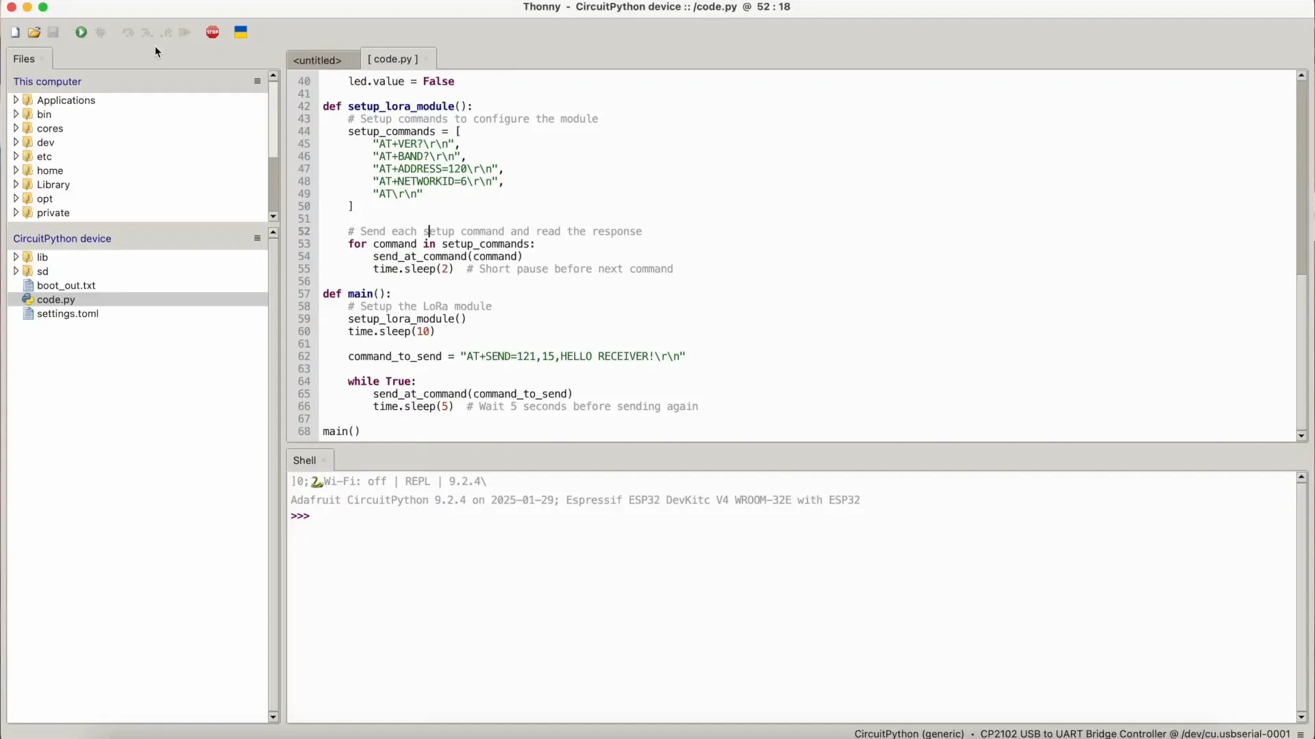
def main():
# Setup the LoRa module
setup_lora_module()
time.sleep(10)
command_to_send = "AT+SEND=121,15,HELLO RECEIVER!\r\n"
while True:
send_at_command(command_to_send)
time.sleep(5) # Wait 5 seconds before sending again
main()
This code sets up the LoRa module on the sending node and sends a message every five seconds. You can easily modify the message or the timing as needed.
Implementing the Receiving Node
Similarly, the receiving node will listen for incoming messages. Here’s a quick look at its setup:
import time
import board
import busio
# Define the pins used for UART communication
UART_TX = board.IO17 # TX2
UART_RX = board.IO16 # RX2
# Initialize UART
uart = busio.UART(UART_TX, UART_RX, baudrate=115200, timeout=0.1)
# Function to send AT commands and read response
def send_at_command(command):
"""Send AT command and read response."""
print(f"Sending: {command.strip()}")
uart.write(bytes(command, "utf-8"))
# Give time for the response
time.sleep(1)
# Read response
response = uart.read(64) # Modify buffer size as needed
if response is not None:
print(f"Response: {response.decode('utf-8').strip()}")
else:
print("No response received")
def setup_lora_module():
# Setup commands to configure the module
setup_commands = [
"AT+VER?\r\n",
"AT+BAND?\r\n",
"AT+ADDRESS=121\r\n",
"AT+NETWORKID=6\r\n"
]
# Send each setup command and read the response
for command in setup_commands:
send_at_command(command)
time.sleep(2) # Wait before sending next command
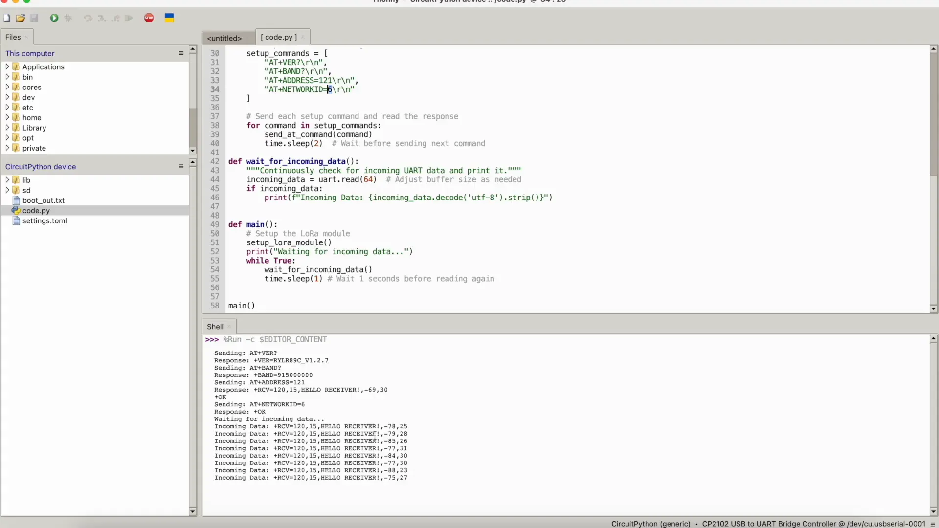
def wait_for_incoming_data():
"""Continuously check for incoming UART data and print it."""
incoming_data = uart.read(64) # Adjust buffer size as needed
if incoming_data:
print(f"Incoming Data: {incoming_data.decode('utf-8').strip()}")
def main():
# Setup the LoRa module
setup_lora_module()
print("Waiting for incoming data...")
while True:
wait_for_incoming_data()
time.sleep(1) # Wait 1 seconds before reading again
main()
This code initializes the LoRa module and prints out any messages received. It’s a simple yet effective way to demonstrate data transfer between the two nodes.
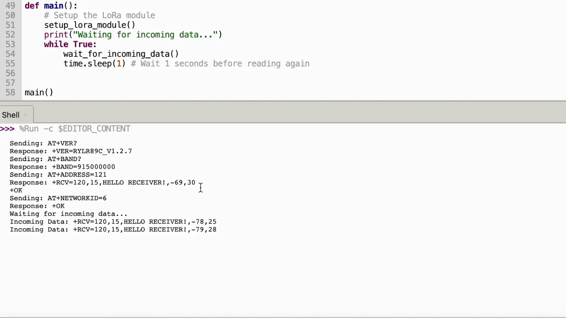
Testing the Setup
Once both nodes are powered and running, you should see the sending node transmitting messages every five seconds, and the receiving node printing those messages to the console. This setup showcases the capabilities of LoRa communication and how easily you can establish a connection between two devices.
Remember that the distance between the nodes can be significant, making this technology ideal for remote sensor applications, GPS tracking, and more.
Common Issues and Troubleshooting
During the setup, you might encounter some common issues:
- No response from the chip: Ensure that your connections are secure and that the proper baud rate is set.
- Messages not being sent: Check the address and network ID configurations.
- Intermittent communication: This could be due to environmental factors affecting the LoRa signal. Ensure that there are minimal obstructions.
With these tips, you should be able to troubleshoot any issues that arise during your setup.
Conclusion
Raw LoRa communication using the SX1276 chip opens up a world of possibilities for IoT applications. Whether you’re creating remote sensors, GPS trackers, or custom devices, the flexibility and range of LoRa technology are unmatched.
Don't hesitate to explore further and experiment with different configurations. The potential is vast, and the applications are limited only by your imagination!
FAQ
What is LoRa technology?
LoRa is a long-range, low-power wireless communication technology that allows devices to communicate over long distances while consuming minimal power.
How far can LoRa communicate?
The communication range can vary significantly based on environmental factors, but LoRa can typically reach distances of several miles in open areas.
What are some applications of LoRa?
LoRa technology is widely used in IoT applications, including remote sensing, GPS tracking, smart agriculture, and more.
Can I use LoRa for real-time communication?
While LoRa is great for transmitting small amounts of data over long distances, it may not be suitable for applications requiring real-time communication due to its lower data rates.
Further Reading
If you're interested in learning more about LoRa technology and its applications, check out the following resources: